 | MiST |

|
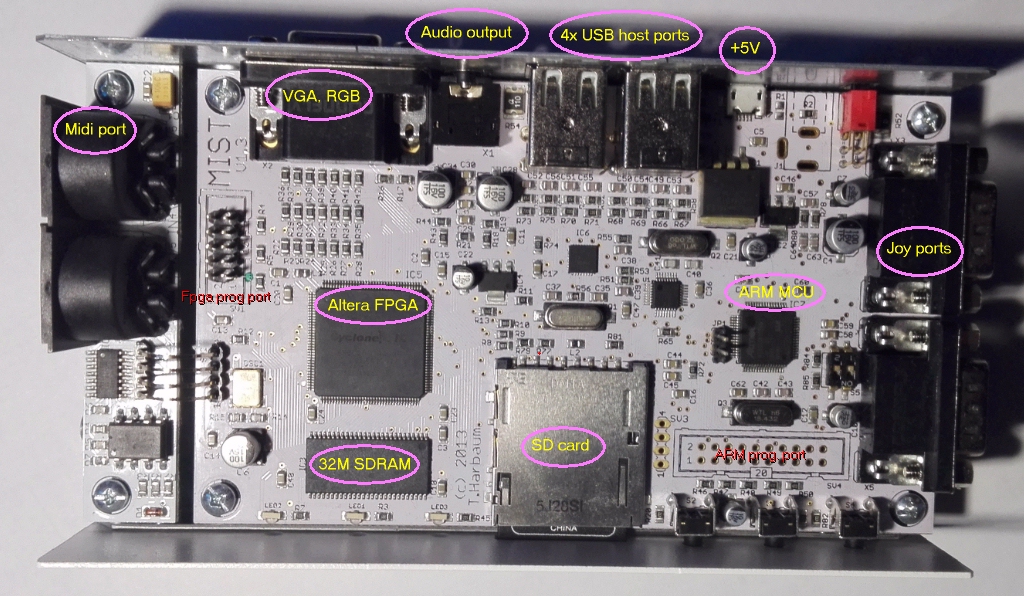 Click on the image to zoom in |
Main parts of the MiST:
|
The FPGA on the MiST board is large enough to hold an entire retro computer inside, including CPU and custom chips, some memory, too. If the target machine needs more than the FPGA internal memory, the external SDRAM can be used. The 3x6 bits RGB can be called "hi-color" as it's able to display 262144 colours.
Via the ARM MCU, different USB devices can be connected to the system, such as keyboards, mouses, game controllers, even USB ethernet interfaces.
Some word about the MiST implementations
Just as we do with real chips, we need to create and connect the internal parts inside the FPGA, too. So in most cases we need a CPU, address decoders, video and audio modules, plus the operative memory. The Altera FPGA on the MiST is a big one. Even though it's not the latest technology, still, it can hold all the custom chips and the CPU of an Amiga or Atari ST. So if you want to realize a smaller 8 bits computer, like C64 and its competitors, they will surely fit. CPU
CPU
Most of the CPUs that were popular in the 80's and 90's are available now in "soft core" version. These are written in Verilog or VHDL, and can be downloaded from
opencores.org.
You find soft core Z80, 6502, 8085, Motorola 68000, even some x86s. Soft core CPUs are more or less cycle compatible with the original ones. There are some differences for sure,
but still, they are great. Inside the FPGA there would be differences anyway. Don't forget that there are 20-30 years between the technology now and back then.
For example, inside an FPGA you don't need bi-directional buses or high-impedance states. A very common (and recommended) method is using Clock Enable signals. So for example your CPU can be halted with this signal, and the buses via multiplexers are available. A DMA cycle or video contended memory access solution will be different from the solutions in the 80's.
The bottom line is that there are usable free soft core CPUs, you only need to wire them, and they'll work.
 Memory
FPGAs usually have some high-speed internal memories. They usually limited, the purpose of the internal memory is not to be used as RAM, but creating FIFOs,
CACHEs, small buffers. MiST's FPGA has around 64K internal static RAM. You might think that this should be enough for a typical Z80 system, but unfortunately, most of the
times it's not the case. A couple of other components need some internal memory, too, like the On Screen Display or the Scan Doubler modules. If you want to use them (you
often do), the internal memory will be less than what your target system needs.This is why there is a big SDRAM on the board. Controlling the SDRAM is a bit complicated, surely more work than using a Static RAM. Fortunately there are solutions available (in the sources for other cores), so one can use it without too much pain. Speed is also limited, the SDRAM random access is around 60-70ns. This does not sound much, but will be enough for old systems. (In BURST mode the SDRAM would be significantly faster, but that mode is not the best for older computers, I am afraid.)
In my solutions I use both the internal and the external RAM, too. Internal ram is good for a video memory for example (if fits), while external SDRAM is good for the traditional RAM for a system. The SDRAM controller for the MiST needs 8 cycles for a random access and the RAM clock can go up to 133 MHz. This is not that bad at all.
See this example: your ZX Spectrum's master clock is 14MHz (this is what the ULA gets, double of the pixel clock). It can be multiplied by 8, resulting the SDRAM clock as 112MHz. Fits. It actually means that your Spectrum CPU could run at 14MHz without any problem. Four times more than the original Spectrum had.
 Custom Chips
When you reimplement an old machine in an FPGA, the real task is to "rewrite" the custom chips of the target machine. As you can see above, putting together a basic
8bits system (CPU, RAM, address decoding) is not really a challenge if you have the parts already (and you do). An expreienced designer can build such a system in 20-30
minutes.But, if you want (cycle exact) sound and video, this is the real task.
Some soft core solutions are also around in this field. From opencores.org you can download sound and video chip cores. For example, a Spectrum ULA or an AY8910 can be found easily, VGA controllers, too. Even some SID implementations available (though none of them perfect afaik).
Obviously there will be always custom chips that you need to create yourself.


 Keyboard, mouse, joystick
Handling the I/O devices is one of the main task for the on board ARM MCU. This MCU configures the FPGA, and handles the connected devices. With four USB host port,
many device can be connected. There are two classic DB9 joy port for old digital joysticks. Everything is handled by the ARM MCU, and the states of these devices sent to the
FPGA via an SPI interface. There is a pre-written Verilog module called user_io, which accept the SPI messages. You can connect it to your system relatively easily. then the I/O devices will be available for the FPGA. The keyboard and the mouse seems like they were PS/2 devices from the FPGA point of view. A convenient way for the developers, thanks to the MiST designer Till Harbaum.
 File system
The file system on the MiST board is the SD card, driven by the ARM MCU. The SD card must contain the FPGA cores for different machines, ROMs, games and other files, basically everything.
MiST provides some different ways to the cores to handle the SD card. For loading ROMs and games into a core, there is a module called DATA_IO. With this module the file loading
is really simple, you don't need to take care of the file system at all, just get the bytes from a selected file. On the other hand, if you need more than that (e.g. want to SAVE something), an SD Card module is there, but this one only handles the low level requests, so you need to implement a file system driver yourself in the target system. The file system on the SD card is FAT32, there are many free applications to handle this, so it's not impossible. But definitely more work than the other way using the module DATA_IO.

 Video and audio outputs of the MiST board
The audio output is a simple (stereo) RC filter, driven by a delta/sigma DAC converter.
Nothing more to write about it. Works well. Period. What is more interesting is the video output.The video output on the MiST is a 3x6 bits RGB output with the tow sync signals. It it capable to produce VGA signals, but not limited to this. Also it can produce RGB signals with different frequency, or even more complex signals, like component (YPbPr) or composite (CVBS) video.
My favourites are the VGA signal and the PAL compatible RGB+Sync output. The latter is mainly for old RGB monitors (e.g Commodore 1084S, CM8833) and European TVs. In Europe the connector called Euro Scart is a standard connector, almost every TV has it. However it is considered obsolete now in the age of HDMI, it!'s still around.
In the 80's-90's most of the home computers (in Europe) generated PAL signals. There was an RF modulator as well, but the picture quality on that was horrible. Compsite PAL signals were a bit better, and analogue RGB (+sync) was even better. Fortunately this is the one that a TV can accept via Euro Scart today. We all know that this connector will vanish, but as long as it's available, we can use it.
The next option is a VGA monitor. Too bad that the VGA standard differs from the PAL in many ways, so it will not be perfect, never ever. Let's see the differences:
- Line frequency: PAL=15.6KHz, VGA=31.2KHz
- Frame frequency: PAL=50 Hz, VGA=60 Hz
- Number of raster lines: PAL=625 lines (2 fields), VGA=525 lines
So either you create a non-standard VGA signal with 625 lines or drop 100 lines somehow. The second option will produce a good VGA signal, but your implementation surely will not be cycle exact to the original machine. Either way it's a compromise somewhere.
My opinion is that if you would like to produce authentic picture, use a Scart cable and an TV that can use that RGB+Sync signal. Read about it here .
 Available MiST modules
I already mentioned some of these. Really helpful Verilog modules help us to realize 8 bits machines.
- SDRAM controller: handles the internal cycles of the SDRAM and provides a simplified interface to the design as if it was static RAM. Attention should be paid to the speed limitation when used (60-70ns per 16bits random read and write). Some guidelines must also be followed, see the MiST pages for more details.
- USER_IO controller: handles the connected I/O devices. A convenient solution for keyboards, mouses, joysticks. This module is also connected to the SD card module, so the file read and write is also done by this in some cases.
- OSD: On Screen Display. Shows the OSD menu, which is handled by the ARM MCU.
- DATA_IO module: responsible for fast data loading. It is a one way direction, it loads files from the SDCARD into the memory. You can use this to load ROM files or games, snapshots, etc. All can be done without any deeper SD card operation. Neat.
- SDCARD for real SD card applications, where loading is not enough. It shows the SDCARD as if it was connected directly to the FPGA. Whereas we do know, it's connected to the ARM, and then the ARM emulates it. Nevertheless, the FPGA will not recognize the difference.
- SCANDOUBLER module: doubles the scan lines. This is the module that you use to convert PAL video signals to VGA signals. It does not change the number of scan lines, so it it not a perfect "scaling" though. The result may or may not work with your VGA monitor. It depends.
[Home] [FPGA development]